google.com, pub-1990720073119592, DIRECT, f08c47fec0942fa0 FIXLEDTV: September 2023

Thursday, September 28, 2023

TCL LED65E5700UDS

 TCL LED65E5700UDS Firmware 

Available Firmware Version is

Version V8-M901K01-LF1V076


Firmware Version V8-M901K01-LF1V076

Problem: Solution Stuck or Freezing at main Logo Screen

LED TV Restart During LOGO Freezing 


TCL Firmware Available 


Bonjour à tous les amis Bonne journée à tous les amis, c'est mon blog électronique pour tous les amis de ce blog. Je peux essayer de décrire l'écran de réparation du téléviseur LED concernant  

La réparation d'écran et les modifications de contournement de panneau sont mon sujet préféré. Je peux également vous fournir le firmware Android TV.


Tuesday, September 26, 2023

Samsung LED TV Repair


style="display:block"
data-ad-client="ca-pub-1990720073119592"
data-ad-slot="8296473633"
data-ad-format="auto">


style="display:block"
data-ad-client="ca-pub-1990720073119592"
data-ad-slot="7445823758"
data-ad-format="auto">


 Model: Samsung UNxxC9000 LED TV


Symptom: The UNxxC9000 LED TV power up sequence
Repair/Solution:
This power up sequence can help you troubleshoot the UNxxC9000, here is the power up:
a. When the AC cord is plugged in, the voltage on the STBY pin goes to 5.3V.
b. The MCU (Microcontroller, Micon &etc) on the mainboard actively looks for the user to press Power On switch from remote control or the TV itself.
c. When a user presses Power, the MCU sends a “High” voltage (0-1.2V transition) to the SMPS/PSU via Power_On/Off pin to activate the rest of the voltages.
d. After the 0-1.2V transition on the POWER_On/Off pin, the following voltages are activated on CNM801 and the “Melody” plays.
- Vamp= 18VDC
- OD_On/Off= 3.3V
- D5.3V = 5V
- D12V = 13V
e) Approximately two seconds later, 5V is applied to the BLU_On/Off pin.
f) Once the BLU_On/Off pin is activated, the LED arrays turn on. CNL801 supplies high voltage to the LED arrays. The following voltages are activated on CNL801 (with respect to chassis GND):
- BOT1+ = 170VDC
- BOT1- = 45VDC
- TOP1- = 45VDC
- TOP1+ = 170VDC
- TOP2+ = 170VDC
- TOP2- = 45VDC
- BOT2- = 45VDC
- BOT2+ = 170VDC
g) High voltage is applied to the panel LED arrays though connectors CN401 and CN402:
Pin 1 and 12
-Approximately 170VDC (when referenced to the chassis GND).
-Voltage varies when referenced to connector GND.
Pin 6 and 7
-GND (effective).
-Approximately 45VDC when the backlight is lowest.
-GND Pins
-GND Potential is highest when signal is >90% duty cycle (almost DC).
-GND Potential is lowest when signal is <10% duty cycle (almost GND).
-Level is controlled by the mainboard though the Bot_Dim and Top_Dim pins on connector CNM801


Model: Samsung LN19C350DXZA LCD TV
Symptom: Display is completely Green color only.
Repair/Solution:
LVDS cable not properly inserted or dirty in the contact pins. Clean the LVDS cable contact pins and connect it back properly.


Model: Samsung UN46C6300SF LED TV
Symptom: No Power
Repair/Solution:
This ICB801 (ICE3BR1765J) Power IC is defective on the PSU board.


Model: Sharp LC26SA1E, LC26SD1E, LC32SA1E, LC32SD1E, LC42SA1E, LC42SD1E LCD TV
Symptom: No Display, Sound Problem or Various operational key issues
Repair/Solution:
If after checking the whole PCB boards in TV still not solve the problem, it could be software issues.
Update the main software to the latest version, following the instructions in the service manual. Or using an ISP Programmer to empty their EEPROM IC first, if problem still the same, then you should program their flash memory by ISP Programmer with the working firmware.


Model: Sharp LC46D78UN & LC52D78UN LCD TV
Symptom: HDMI Connectivity Issues: No Sound or No Display When Turned On
In some cases, when connected via HDMI to an external audio amplifier or set top box an interruption to the sound and display may result when the TV us turned off and back on. This may occur due to current leakage from the HDMI-SW IC VHISII9287+-1Q on the mainboard.
Repair/Solution:
When the TV set requires service due to the above mentioned symptom, replace C1614 (0.1uF, 104 ceramic capacitor) on the mainboard with a 1K ohm1/16W resistor to reduce the leakage effect or just replace the mainboard.


LG 32LC56: Picture divided into several parts. Distorted picture
Model: LG 32LC56 LCD TV
Symptom: Picture divided into several parts. Distorted picture
Cure/Solution: Replace T-CON board (Part Number: 218394).

LG 32LC56ZC: No start-up. Standby LED flashes from red to green
Model: LG 32LC56ZC LCD TV
Symptom: No start-up. Standby LED flashes from red to green
Cure/Solution: Replace C202, C206, C217 and C218 (2200uf/10v all), and C226 (470uf/25v).

GOODMANS GTV26WLCD: Shuts down and LED blinks
Model: GOODMANS GTV26WLCD LCD TV
Symptom: Shuts down and LED blinks
Cure/Solution: Replace C877 and C878 (both 15nf/630V) near heatsink, at top left corner of PSU

BUSH LCD26TV006HDX: No display. Flashing standby light
Model: BUSH LCD26TV006HDX LCD TV
Symptom: No display. Flashing standby light.
Cure/Solution: The capacitor C315 (1000uF/25v) is supplied higher rated, and is a little bigger so use longer leads don't fit close to board. Be careful when soldering you don't accidentally remove the tiny surface mount resistors on back of board.

Samsung LN32A330: The TV takes longer to power on than normal
Model/s: Samsung LN32A330J1DXZA,LN32A330J1NXZA LCD TV
Symptom: The TV takes longer to power on than normal
The TV takes longer to power on than normal. You may hear several clicks while the TV attempts to power on.
Cause: The electrolytic in the capacitors on the power supply board over time will dry out causing the power supply to shut down during its initial power on cycle.
Cure/Solutions: Refer to the capacitor cross reference guide below for the list of the capacitors that should be replaced.

Samsung: Unit tries to start with melody but cycles off and back on
Model/s: Samsung LN40A650A1FXZA,LN46A650A1FXZA,LN40A750R1FXZC,LN46A 750R1FXZA,LN40A750R1FXZA LCD TV
Symptom: Unit tries to start with melody but cycles off and back on
Cure/Solutions: If the unit tries to turn on and makes the startup melody but then immediately shuts off and starts again, unplug the LVDS cable and apply power again. If the set stays on, replace the T-Con board.

Samsung: Will not turn on, cycles on and off with startup melody, no backlights
Model/s: Samsung LN52A650A1FXZA,LN40A650A1FXZA,LN46A650A1FXZA,LN52A 650A1FXZC,LN46A650A1FXZC LCD TV
Symptom: Will not turn on, cycles on and off with startup melody, no backlights
Cure/Solutions: If the set will try to turn on and the startup melody sounds but no backlight appears and the set cycles off and on every 5 to 10 seconds, unplug the LVDS cable from the T-Con/FRC board. If the set then runs and the backlights come on and stay on, replace the defective T-Con/FRC board.

Samsung LNS4692: No video TV, has backlight and audio. TV will not come on
Model/s: Samsung LNS4692DX/XAA LCD TV
Symptom: No video TV, has backlight and audio. TV will not come on.
Cure/Solutions: Found pico fuse open at cp1 on the T-CON pcb short cp1 TV comes on runs fine. Replace the T-CON pcb.

Samsung: Standby light is on, flashes once briefly then unit attempts to turn on
Model/s: Samsung LN32A330J1DXZA,LN32A450C1DXZA,LN32A550P3FXZA,LN32A 540P2DXZA,LN32A330J1NXZA,LN32A450C1HXZA,LN32A450C3 HXZA, LN32A300J1DXZA LCD TV
Symptom: Standby light is on, flashes once briefly then unit attempts to turn on
Cure/Solutions: If the unit will not turn on, but the red standby LED is on and flashes once quickly when the power button is pressed on the remote or the TV, the 2200uf 10v filter capacitor on the SMPS has failed. This capacitor is located in the upper right side of the power supply close to the cable that connects the main board. Visual inspection will normally show that it has a swollen top. Replace capacitor and inspect the others in the filter stage to restore operation.

Monday, September 25, 2023

Wansa TV 65-inch UHD Smart LED WUD65JOA63S Firmware


Wansa TV 65-inch UHD Smart LED WUD65JOA63S Firmware 


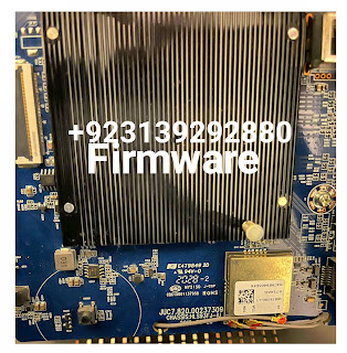
Main Board Number JUC7.820.00237309 Firmware 


Main Board Number JUC7.820.00237309 Firmware 

Upgrade Version 9 to Version 11

USB Upgradeable Firmware Available 

Problem Solution: LED TV Stuck On Main Logo

LED TV Freez and Stuck Not Coming on main Window


Firmware Upgrade Version 9 to Version 11

Google Update

Google GTV Apps Update 

Buy With PayPal 

For International Buyers

Buying link   

For Pakistan User's

Contact 0313-9292880 WhatsApp

+923139292880


Wansa TV 65-inch UHD Smart LED WUD65JOA63S Firmware

Wansa TV 65-inch UHD Smart LED WUD65JOA63S Firmware 


Main Board Number JUC7.820.00237309 Firmware 

Upgrade Version 9 to Version 11

USB Upgradeable Firmware Available 

Problem Solution: LED TV Stuck On Main Logo

LED TV Freez and Stuck Not Coming on main Window


Firmware Upgrade Version 9 to Version 11

Google Update

Google GTV Apps Update 

Buy With PayPal 

For International Buyers

Buying link   

For Pakistan User's

Contact 0313-9292880 WhatsApp

+923139292880


style="display:block"
data-ad-client="ca-pub-1990720073119592"
data-ad-slot="8296473633"
data-ad-format="auto">


style="display:block"
data-ad-client="ca-pub-1990720073119592"
data-ad-slot="7445823758"
data-ad-format="auto">

Sunday, September 24, 2023

CV338H-A42 Firmware


style="display:block"
data-ad-client="ca-pub-1990720073119592"
data-ad-slot="8296473633"
data-ad-format="auto">


style="display:block"
data-ad-client="ca-pub-1990720073119592"
data-ad-slot="7445823758"
data-ad-format="auto">


CV338H-A42 TV Board Firmware is For Download Free


CV338H-A42 this is a smart android tv board. This article Is about the firmware of this smart android board. I will provide you CV338H-A42 board software.

I already share my paid softwares on this site. Software means Firmwares

  • Main Board: CV338H-A42-K39 Combo Board
  • Solution: MSD6A338ST-003J
  • Video System: PAL
  • Sound System: BG, I, D, K
  • Receiving Channel : ATV: 200 (1~200)
  • HDMI : 480i, 480p, 576i, 576p, 720p, 1080i, 1080p
  • HDMI Support: HDMI-1.4a, HDcp-1.4
  • HDMI CEC/ARC Support: Yes
  • USB Support: USB2.0
  • YPbPr/ YCbCr: No
  • AC Input (Normal) : 100~240V AC 50/60Hz
  • AC Input (Range) : 90~264V AC 50/60Hz
  • Management : Low power consumable mode (Stby <0.5W)
  • Power Consumption : <75W
  • RF Input : 1
  • AV IN : 2 (RCA)
  • HDMI (CEC & ARC) : 2
  • USB : 2
  • VGA+PC Ain : 1
  • Coax : 1 (RCA)
  • RJ45 : 1
  • Line Out: RCA (L & R)
  • Key Function : Vol+/-, CH+/-, Menu, Source, Power
  • Audio Output: 2x10W
  • Speaker : 45×128, 8E/12W-SV-1294(Box Type-Optional)
  • Sound Type: Bottom Firing
  • Stereo: Yes
  • CPU : ARM Cortex A7 Dual Core 1.3GHz
  • GPU : Mali-400MP2
  • RA : 1GB
  • Storage : 8GB (Internal)
  • Android : 8
  • Network : RJ45 Ethernet Support (10/100M, DHCP)
  • RJ45: 10/100M, DHCP
  • WiFi : IEEE 802.11 b/g/n
  • Browser : HTML5 Webpage Supports
  • USB : 2*USB2.0
  • HDMI: 1.4a
  • RTC : Yes (Internet Clock)
  • OSD Language : English
  • Chipset: MSD6A338ST-003J
  • Surfing Net: Wireless Mouse and Keyboard (Optional)


CV338H-A42 board firmware Step of USB reorganize

  1. Put the firmware "CV338H-A42.crate" in an empty U-disk, behind totaling the U-disk to the board.
  2. After reduction of view concerning speaking the triumph, the roomy of the 7key button will be Red innovative flash red and blue.after regarding 1 minute, the ably-ventilated approach of view damage, 
  3. It means add together has curtains. (Note that write board firmware programs don't facility outages, crashing won't be sprightly to use)
  4. If you can't p.s. judgment your screen model number in the book, you can copy anyone same reach to plan, if not intended, take objective added one.
  5. How to into Factory aerate?
  6. Press the "Menu" button with press"1 1 4 7


Resolution 1366x768 Samsung Remote 

Download Link here 


Saturday, September 16, 2023

5800-A9K53G-0P10 Firmware Available


 Genuine Main Board Skyworth 5800-A9K53G-0P10 Firmware Available

Problem Solved 

Stuck on logo

Restarting After Stuck at main logo

Flashing Old Firmware

With Updated Firmware 


Redeem Your Bonus Points of Downloading 


Skyworth Main boards 5800-A9K53G-0P10 is use in 5 Different Models You can use this Firmware without any tension with same remote working 


Contact my WhatsApp+923139292880


5800-A9K53G-0P10 Firmware Available


style="display:block"
data-ad-client="ca-pub-1990720073119592"
data-ad-slot="8296473633"
data-ad-format="auto">


style="display:block"
data-ad-client="ca-pub-1990720073119592"
data-ad-slot="7445823758"
data-ad-format="auto">


 Genuine Main Board Skyworth 5800-A9K53G-0P10 Firmware Available

Problem Solved 

Stuck on logo

Restarting After Stuck at main logo

Flashing Old Firmware

With Updated Firmware 


Skyworth Main boards 5800-A9K53G-0P10 is use in 5 Different Models You can use this Firmware without any tension with same remote working 


Contact my WhatsApp+923139292880


Friday, September 15, 2023

Circuit Short Killer Tricks


 Circuit Short Killer 

A circuit short killer refers to a device or technique used to identify and troubleshoot circuit shorts in electrical systems.

It helps in locating and fixing the faulty circuit that is causing the short circuit.

Redeem Your Bonus Points of Downloading 

Here are a few common methods used to find circuit shorts:


1.

Visual inspection: Start by visually inspecting the electrical system, including wires, cables, connectors, and any exposed or damaged areas.

Look for any signs of burned or melted insulation, exposed wires, or loose connections.


2.

Circuit breaker test: Turn off all the circuit breakers in the electrical panel and then turn them on one by one.

If a circuit breaker trips immediately after turning it on, it often indicates a circuit short in that particular circuit.


3.

Multimeter testing: Use a multimeter to test the resistance, continuity, and voltage at different points in the circuit.

Compare readings between different components to identify any variations that may indicate a short circuit.


4.

Divide and conquer: If the circuit has multiple devices or outlets, disconnect them all and then reconnect them one by one, testing for a short circuit after each connection.

This helps to isolate the problematic device or outlet.


5.

Short circuit locator: There are specialized tools called short circuit locators or circuit tracers available in the market.

These tools emit a signal that can be traced along the length of a circuit to pinpoint the location of the short circuit.


Remember, working with electrical systems can be dangerous.

If you are not confident or experienced in electrical work, it is recommended to seek professional help from a licensed electrician or technician.


6: Short Circuit Remover Tools

You can remove short circuit in electronics circuit by short killer tools as shown in this pictures 


Dead, means No output and no response on output.


Missing particular voltage.


Voltage fluctuation.


Shorting in the primary section.


Secondary section shorting.


Main Capacitor Blast and weak.


STR Mosfet error.


Blast STR IC.


These are the common fault which we get in the LCD LED TV. Now I will tell you how you can fix this type of fault very easily. I already repair many power supply board. If you want to watch my PSU repairing video click here and learn how I repair power supply and fix the TV.


Repairing Process


DEAD: For dead power supply repairing first of all you have to check all the components. Mostly PSU getting dead when some components getting overheating or burn. Find the bad components and replace them with a new one. Especially mostly time we get a fault in the main STR Transistor which use for voltage switching. And lastly you have to check the feedback Schottky diode. Many times this diode also getting overheat and burn, after that stop the voltage flow. for more information click here.


Missing Particular Voltage: When you get some specific particular voltage is missing in the PSU, you have to check that track. For example from PSU we get many values voltage like 5v, 3.3v, 12v, 24v. If any of this voltage is missing in the LCD LED power supply, check that particular voltage which you not getting from PSU. This type of specific voltage missing problem you fix very easily if you know about tracing the track. Mostly I fixed this type of problem by doing to replace the capacitor and transistor and voltage regulator replacing.


Voltage Fluctuation: This means the output voltage is not stable and not pure DC. To repair this type of fault you have to check the voltage rectification section. Firstly check the main primary section capacitor. Seeing such a rectification problem for this fault. This type of problem also arises because the capacitor is weak. If the capacitor is getting weak simply replace that capacitor. Your LCD LED TV Power supply fluctuation problem will be fixed.


Shorting in Primary and Secondary Section: It is very simple to fix this type of shorting problem. Only you have to find out the sorting components and replace them with a new one. That’s it your power supply will be fixed.


Main Capacitor Blast and weak: High voltage damage in LCD LED power supply is that blast the main capacitor or blast the main STR Transistor. When you open the TV first you will see the capacitor is a blast. This problem only gets when a huge amount of voltage will flow in the circuit. For repairing this problem first change the fuse and capacitor. Before the test the circuit also checks the STR Transistor. Many times STR also effected by the overvoltage input signal.


STR Mosfet error: This is most getting a problem in the LCD LED power supply. If you get 10 Dead LED TV for repairing, 6 will be the STR error problem. In my 12 years of repairing experience I have repaired 1000+ 


Contributor SK Electronics


Thank You


Circuit Short Killer Tricks


 Circuit Short Killer 

A circuit short killer refers to a device or technique used to identify and troubleshoot circuit shorts in electrical systems.

It helps in locating and fixing the faulty circuit that is causing the short circuit.


Here are a few common methods used to find circuit shorts:


1.

Visual inspection: Start by visually inspecting the electrical system, including wires, cables, connectors, and any exposed or damaged areas.

Look for any signs of burned or melted insulation, exposed wires, or loose connections.


2.

Circuit breaker test: Turn off all the circuit breakers in the electrical panel and then turn them on one by one.

If a circuit breaker trips immediately after turning it on, it often indicates a circuit short in that particular circuit.


3.

Multimeter testing: Use a multimeter to test the resistance, continuity, and voltage at different points in the circuit.

Compare readings between different components to identify any variations that may indicate a short circuit.


4.

Divide and conquer: If the circuit has multiple devices or outlets, disconnect them all and then reconnect them one by one, testing for a short circuit after each connection.

This helps to isolate the problematic device or outlet.


5.

Short circuit locator: There are specialized tools called short circuit locators or circuit tracers available in the market.

These tools emit a signal that can be traced along the length of a circuit to pinpoint the location of the short circuit.


Remember, working with electrical systems can be dangerous.

If you are not confident or experienced in electrical work, it is recommended to seek professional help from a licensed electrician or technician.


6: Short Circuit Remover Tools

You can remove short circuit in electronics circuit by short killer tools as shown in this pictures 


Dead, means No output and no response on output.


Missing particular voltage.


Voltage fluctuation.


Shorting in the primary section.


Secondary section shorting.


Main Capacitor Blast and weak.


STR Mosfet error.


Blast STR IC.


These are the common fault which we get in the LCD LED TV. Now I will tell you how you can fix this type of fault very easily. I already repair many power supply board. If you want to watch my PSU repairing video click here and learn how I repair power supply and fix the TV.


Repairing Process


DEAD: For dead power supply repairing first of all you have to check all the components. Mostly PSU getting dead when some components getting overheating or burn. Find the bad components and replace them with a new one. Especially mostly time we get a fault in the main STR Transistor which use for voltage switching. And lastly you have to check the feedback Schottky diode. Many times this diode also getting overheat and burn, after that stop the voltage flow. for more information click here.


Missing Particular Voltage: When you get some specific particular voltage is missing in the PSU, you have to check that track. For example from PSU we get many values voltage like 5v, 3.3v, 12v, 24v. If any of this voltage is missing in the LCD LED power supply, check that particular voltage which you not getting from PSU. This type of specific voltage missing problem you fix very easily if you know about tracing the track. Mostly I fixed this type of problem by doing to replace the capacitor and transistor and voltage regulator replacing.


Voltage Fluctuation: This means the output voltage is not stable and not pure DC. To repair this type of fault you have to check the voltage rectification section. Firstly check the main primary section capacitor. Seeing such a rectification problem for this fault. This type of problem also arises because the capacitor is weak. If the capacitor is getting weak simply replace that capacitor. Your LCD LED TV Power supply fluctuation problem will be fixed.


Shorting in Primary and Secondary Section: It is very simple to fix this type of shorting problem. Only you have to find out the sorting components and replace them with a new one. That’s it your power supply will be fixed.


Main Capacitor Blast and weak: High voltage damage in LCD LED power supply is that blast the main capacitor or blast the main STR Transistor. When you open the TV first you will see the capacitor is a blast. This problem only gets when a huge amount of voltage will flow in the circuit. For repairing this problem first change the fuse and capacitor. Before the test the circuit also checks the STR Transistor. Many times STR also effected by the overvoltage input signal.


STR Mosfet error: This is most getting a problem in the LCD LED power supply. If you get 10 Dead LED TV for repairing, 6 will be the STR error problem. In my 12 years of repairing experience I have repaired 1000+ 


Contributor SK Electronics


Thank You


PWM Regulators Guide


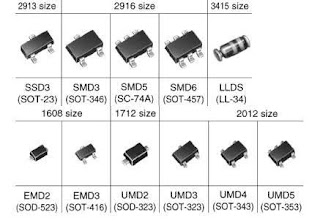
PWM IPS in the housings SOT-23-6, SOT-26, TSOP-6

By Imran Ashraf Khan


In the circuitry of modern pulsed power supplies (SMPS), PWM regulators, made in small-sized planar cases with six terminals, have gained wide popularity. The body type designation can be SOT-23-6, SOT-23-6L, SOT-26, TSOP-6, SSOT-6. The layout and layout of the pins are shown in the figure below. In this case, the left fragment of the picture shows the code marking LD7530A
PWM SOT-23-6
Pin Assignment: 
1 - GND. (Common wire). 
2 - FB. (FeedBack - Feedback). Input for controlling the pulse duration with a signal from the output voltage. Sometimes it can have the designation COMP (input comparator). 
3 - RI / RT / CT / COMP / NC - Depending on the type of chip, it can be used for a frequency-assigning RC circuit (RI / RT / CT) or for protection, as a PWM tripping comparator input with a threshold value at its input, specified in the document. In some types of microcircuits this input can be not involved in any way (NC - No Connect). 
4 - SENSE, different CS (Current Sense) - Input from the current sensor at the source of the key. 
5 - VCC - Input voltage supply and start the chip. 
6th - OUT (GATE) - Output to control the gate of the key.
Functionally similar regulators work on the principle of popular earlier PWM chips xx384x series, which have proved themselves in terms of reliability and stability.
Some difficulties often arise when replacing or selecting an analog for similar PWM controllers due to the use of code marking in the designation of the type of microcircuit. The situation is complicated by a large number of component manufacturers, which do not always provide documentation for mass access, and not all manufacturers of ready-made devices supply repair service centers with circuits, so real repair schemes often have to be studied by repairers on the installed components and wiring connections directly on the board.


In practice, PWM chips and EAxxx and Eaxxx marking codes are often found. Official documents on them are not found in free access, but discussions on the forums and pieces of pictures from the PDF from System General, which publishes them as SG6848T and SG6848T2, have been preserved. The picture is attached.

To the attention of the masters we offer tables made up of information available on the Internet and PDF documents for the selection of analogs when replacing the most common six-legged planar PWM with pinout: pin1 - GND, pin2 - FB (COMP), pin4 - Sense, pin5 - Vcc, pin6 - OUT . 
Their main difference is the application and purpose of the output 3.


PWM controllers (PWM), without using output 3.
NamePart NamberDilerMarking
SG6849SG684965TZFairchild / ON SemiBBxx
SG6849SG6849-65T, SG6849-65TZSystem GeneralMBxx EBxx
SGP400SGP400TZSystem GeneralAAKxx
PWM-regulators (PWM) with the installation of the resistor 95-100 kOhm to pin 3.
Using the PWM listed below, the frequency should be set by the resistor RT (RI) from pin 3 to ground. Usually its rating is chosen 95-100 kOhm for frequency 65-100 KHz. More precisely see the attached documentation. PDF files are packaged in RAR.
NamePart NamberDilerMarking
AP3103AAP3103AKTR-G1Diodes IncorporatedGHL
AP8263AP8263E6R, A8263E6VRAiT SemiconductorS1xx
AT3263AT3263S6ATC Technology3263
CR6848CR6848SChip-Rail848H16
CR6850CR6850SChip-Rail850xx
CR6851CR6851SChip-Rail851xx
FAN6602RFAN6602RM6XFairchild / ON SemiACCxx
FS6830FS6830FirstSemi
GR8830GR8830CGGrenergy30xx
GR8836GR8836C, GR8836CGGrenergy36xx
H6849H6849NFHI-SINCERITY
H6850H6850NFHI-SINCERITY
HT2263HT2263MPHOT-CHIP63xxx
KP201Kiwi Instruments
LD7531LD7531GL, LD7531PLLeadtrendxxP31
LD7531ALD7531AGLLeadtrendxxP31A
LD7535 / ALD7535BL, LD7535GL, LD7535ABL, LD7535AGLLeadtrendxxP35-xxx35A
LD7550LD7550BL, LD7550ILLeadtrendxxP50
LD7550BLD7550BBL, LD7550BILLeadtrendxxP50B
LD7551LD7551BL / ILLeadtrendxxP51
LD7551CLD7551CGLLeadtrendxxP51C
NX1049XN1049TPXian-Innuovo49xxx
OB2262OB2262MPOn-Bright-Electronics62xx
OB2263OB2263MPOn-Bright-Electronics63xx
PT4201PT4201E23FPowtech4201
R7731R7731GE / PERichtek0Q =
R7731AR7731AGERichtekIDP = xx
SD4870SD4870TRSilan Microelectronics4870
SF1530SF1530LGTSiFirst30xxx
SG5701SG5701TZSystem GeneralAAExx
SG6848SG6848T, SG6848T1, SG6848TZ1, SG6848T2Fairchild / ON SemiAAHxx EAxxx
SG6858SG6858TZFairchild / ON SemiAAIxx
SG6859ASG6859ATZ, SG6859ATYFairchild / ON SemiAAJFxx
SG6859SG6859TZFairchild / ON SemiAAJMxx
SG6860SG6860TYFairchildAAQxx
SP6850SP6850S26RGSporton Lab850xx
SP6853SP6853S26RGB, SP6853S26RGSporton Lab853xx
SW2263SW2263MPSamWin
UC3863 / GUC3863G-AG6-RUnisonic Technologies CoU863 U863G
PWM controllers in which pin 3 is used differently.
When using the PWM controllers listed below, you should pay attention to pin 3, which can be used to organize protection - thermal or from exceeding the input voltage. 
The frequency can be fixed at 65kHz, or be set by the capacitor rating on pin 3. 
When replacing any microcircuits with analogs, carefully study the documentation. PDF files are packed in the RAR archive.
NamePart NamberDilerMarking
AP3105 / V / L / RAP3105KTR-G1, AP3105VKTR-G1, AP3105LKTR-G1, AP3105RKTR-G1Diodes IncorporatedGHN GHO GHP GHQ
AP3105NA / NV / NL / NRAP3105NAKTR-G1, AP3105NVKTR-G1, AP3105NLKTR-G1, AP3105NRKTR-G1Diodes IncorporatedGKN GKO GKP GKQ
AP3125A / V / L / RAP3125AKTR-G1, AP3125VKTR-G1, AP3125LKTR-G1, AP3125RKTR-G1Diodes IncorporatedGLS GLU GNB GNC
AP3125BAP3125BKTR-G1Diodes IncorporatedGLV
AP3125HA / HBAP3125HAKTR-G1, AP3125HBKTR-G1Diodes IncorporatedGNP GNQ
AP31261AP31261KTR-G1Diodes IncorporatedGPE
AP3127 / HAP3127KTR-G1, AP3127HKTR-G1Diodes IncorporatedGPH GSH
AP3301AP3301K6TR-G1Diodes IncorporatedGTC
FAN6862FAN6862TYFairchild / ON SemiABDxx
FAN6863FAN6863TY, FAN6863LTY, FAN6863RTYFairchild / ON SemiABRxx
HT2273HT2273TPHOT-CHIP73xxx
LD7510 / JLD7510GL, LD7510JGLLeadtrendxxP10 xxP10J
LD7530 / ALD7530PL, LD7530GL, LD7530APL, LD7530AGLLeadtrendxxP30 xxxP30A
LD7532LD7532GLLeadtrendxxP32
LD7532ALD7532AGLLeadtrendxxP32A
LD7532HLD7532HGLLeadtrendxxP32H
LD7533LD7533GLLeadtrendxxP33
LD7536LD7536GLLeadtrendxxP36
LD7536RLD7536RGLLeadtrendxxP36R
LD7537RLD7537RGLLeadtrendxxP37R
ME8204ME8204M6GMicrOneME8204xx
NCP1250NCP1250ASN65T1G, NCP1250BSN65T1G, NCP1250ASN100T1G, NCP1250BSN100T1GON Semiconductor25xxxx
NCP1251NCP1251ASN65T1G, NCP1251BSN65T1G, NCP1251ASN100T1G, NCP1251BSN100T1GON Semiconductor5xxxxx
OB2273OB2273MPOn-Bright-Electronics73xx
R7735R7735AGE, R7735HGE, R7735GGE, R7735RGE, R7735LGERichtek
UC3873 / GUC3873-AG6-R, UC3873G-AG6-RUnisonic TechnologiesU873 U873G
The table is updated as information becomes available.


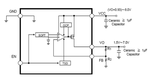
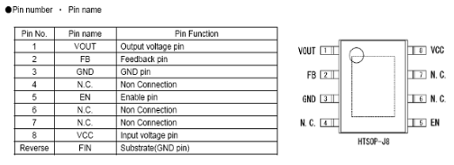
How to read LDO LCD 8-pin regulator code 00HC5W


  • This kind of regulator is often found on the Toshiba LCD motherboard, and the shape is similar to ic eeprom.
  • The BD writing code is not written on the physical ic regulator. So for example just written 00IC0W, 00IA5W

How to read the specs: For example say 00HC5W


(1) Code "00" This means that the output voltage variable or can diajust by changing the value of the feedback resistor. 
(2) The "H" code indicates that the maximum input allowable voltage is 10v. 
(3) The code "C5" indicates that the maximum current capability of 1.5A 

Example usage:
  • Input Voltage: 8.0v
  • Output voltage: 1.5v to 7v - can be obtained by changing the value of R1 / R2
clip_image004
 
clip_image006


6 pin Regulator SMD Chip Codes
6 pin PWM IC code
5xy= NCP1251,
IDP606 = R7731A,
63xxx = OB2263,
WP35/XP35 = LD7535,
ABx = FAN6862,
xxP/50 = LD7550IL_BL,
xxP/50 = LD7550IL_BL
52xxx = OB2252
62xxx = OB2262
73xxx = 0B2273
AAIxx = SG6858TZ
G6G = AP4313
37x = LD7537

Service Manuals Free Downlaods